Complete build tutorial for the HD Sparrow
This guide provides a step-by-step explanation of how to assemble «Le Moineau,» a drone particularly well-suited for beginners in FPV.
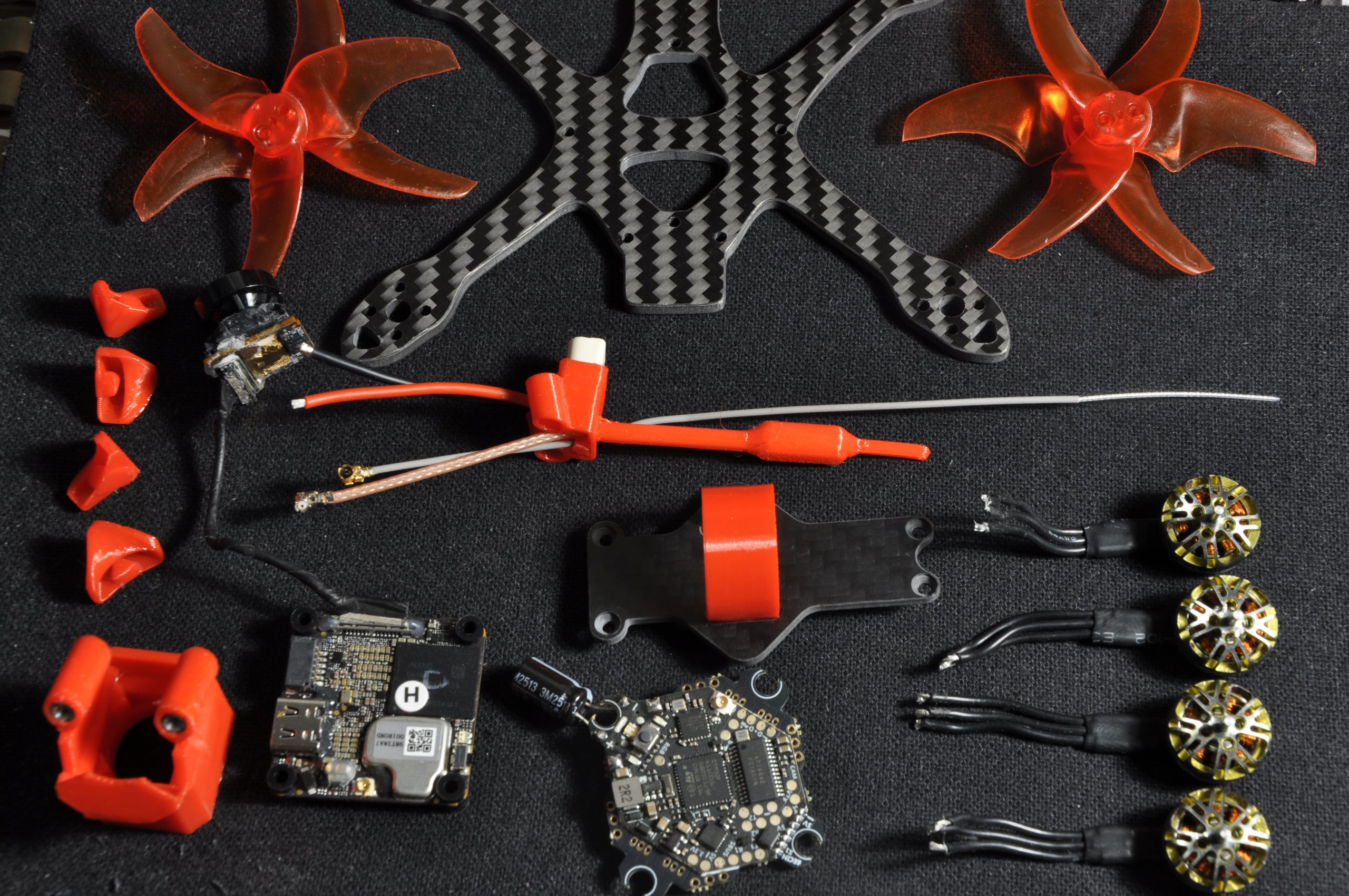
🛒 Required Materials:
- One frame: Le Moineau
- TPU 3D prints (provided with the frame)
- 4 motors (e.g., Sparkhobby 8500kv)
- 2.5" propellers (e.g., AVAN Rush)
- One DJI O4 VTX (see the preparation guide)
- One AIO board, mandatory with integrated RX (e.g., JHEMCU G435 ELRS or Darwin FPV)
🛠️ Tools:
- One 1.5mm hex screwdriver
- Blu-Tack (to hold the board during soldering)
- Heat shrink tubing
- One soldering iron (e.g., Alientek T80)
- Solder (lead-based if possible, to facilitate soldering)
- One pair of wire cutters and one pair of precision pliers
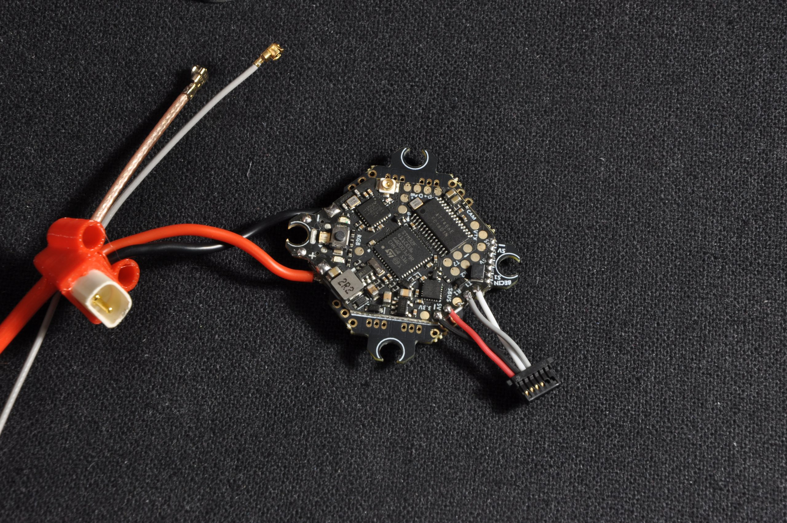
Step 1: Preparation and soldering of the AIO
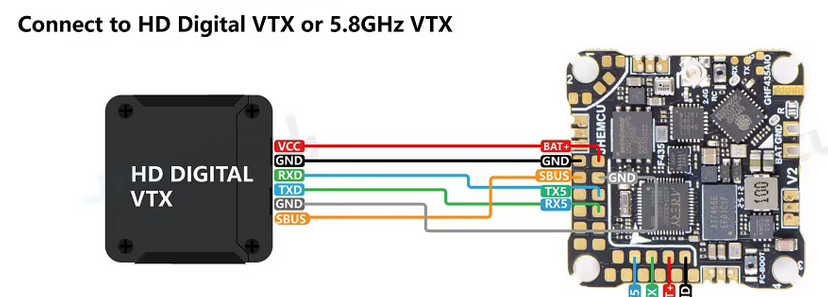
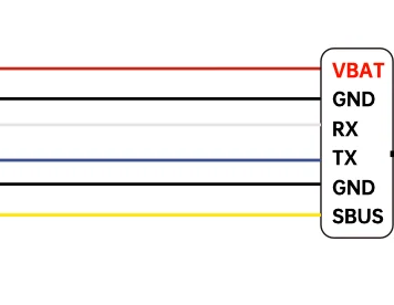
Begin by cutting and soldering the DJI O4 connector directly onto the AIO board. To ensure correct pinout, refer to the board manufacturer's diagram as well as the DJI cable color code.
ℹ️ Note: The yellow wire of the DJI connector is only used if a DJI radio controller is used (which is generally not recommended). It can therefore be removed.
Next, solder the battery connector (pigtail, here a BT3 included in the Moineau kit). Here are the recommendations for successfully completing this demanding solder joint:
- Set the soldering iron to its maximum temperature.
- Generously tin the pad on the board and the wire.
- Heat and assemble the two elements quickly. Prolonged heating risks desoldering adjacent SMD components.
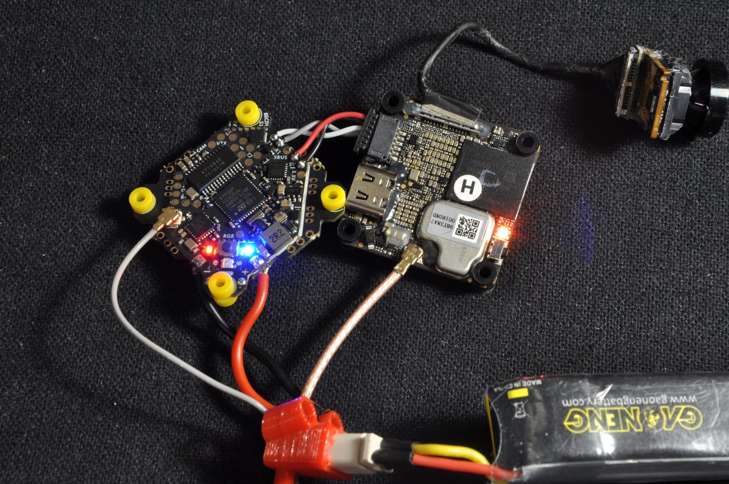
Step 2: Board verification
Before proceeding further, connect the board via USB or battery to verify that everything works (LEDs lighting up). AIO boards of this format can sometimes have factory defects.
⚠️ Warning: As an example, the JHEMCU board initially intended for this build turned out to be defective and had to be replaced with a Darwin FPV model after a refund.
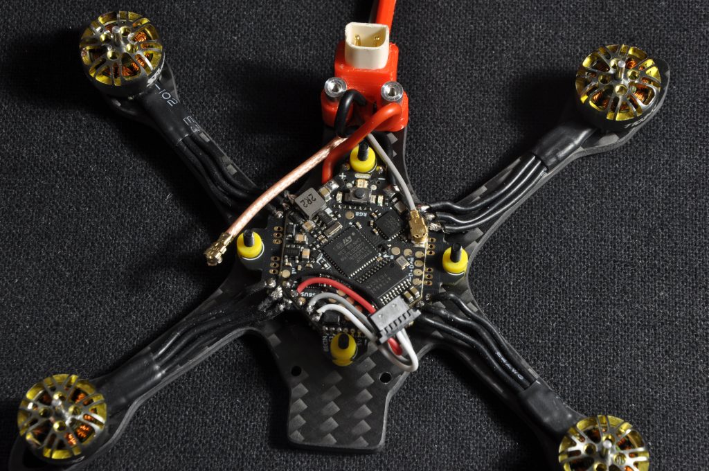
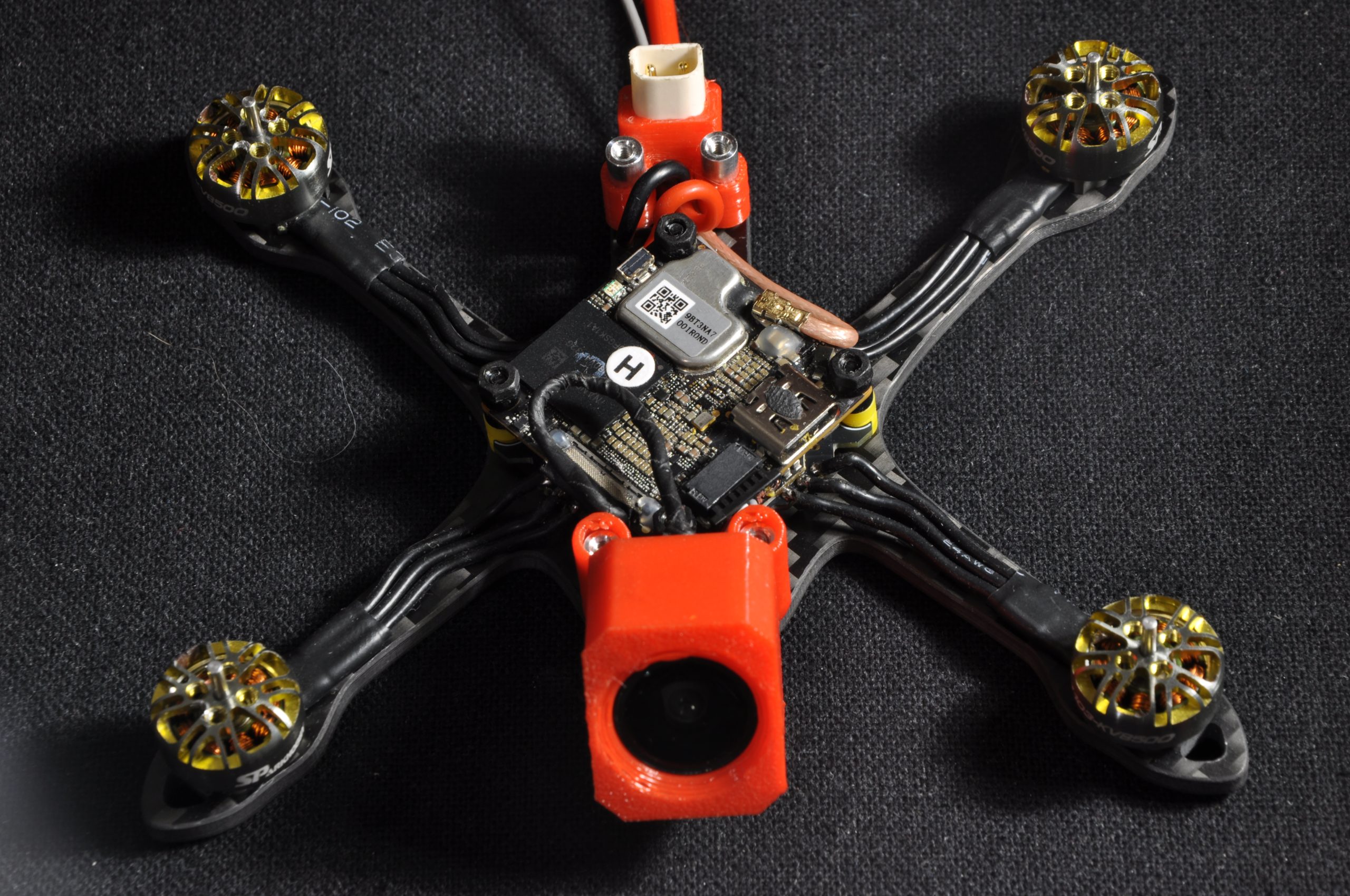
Step 3: Installation of the AIO and motors
Secure the AIO board onto the frame using the nylon screws and nuts. Then screw the motors onto the arms using the 5mm M2 screws (the shortest ones).
Cut the motor wires to the appropriate length, strip them, tin them, then solder them to the AIO pads. Modern ESCs have short-circuit protection: in case of a poor solder joint, the motor will simply refuse to start, allowing the opportunity to correct the setup without damage.
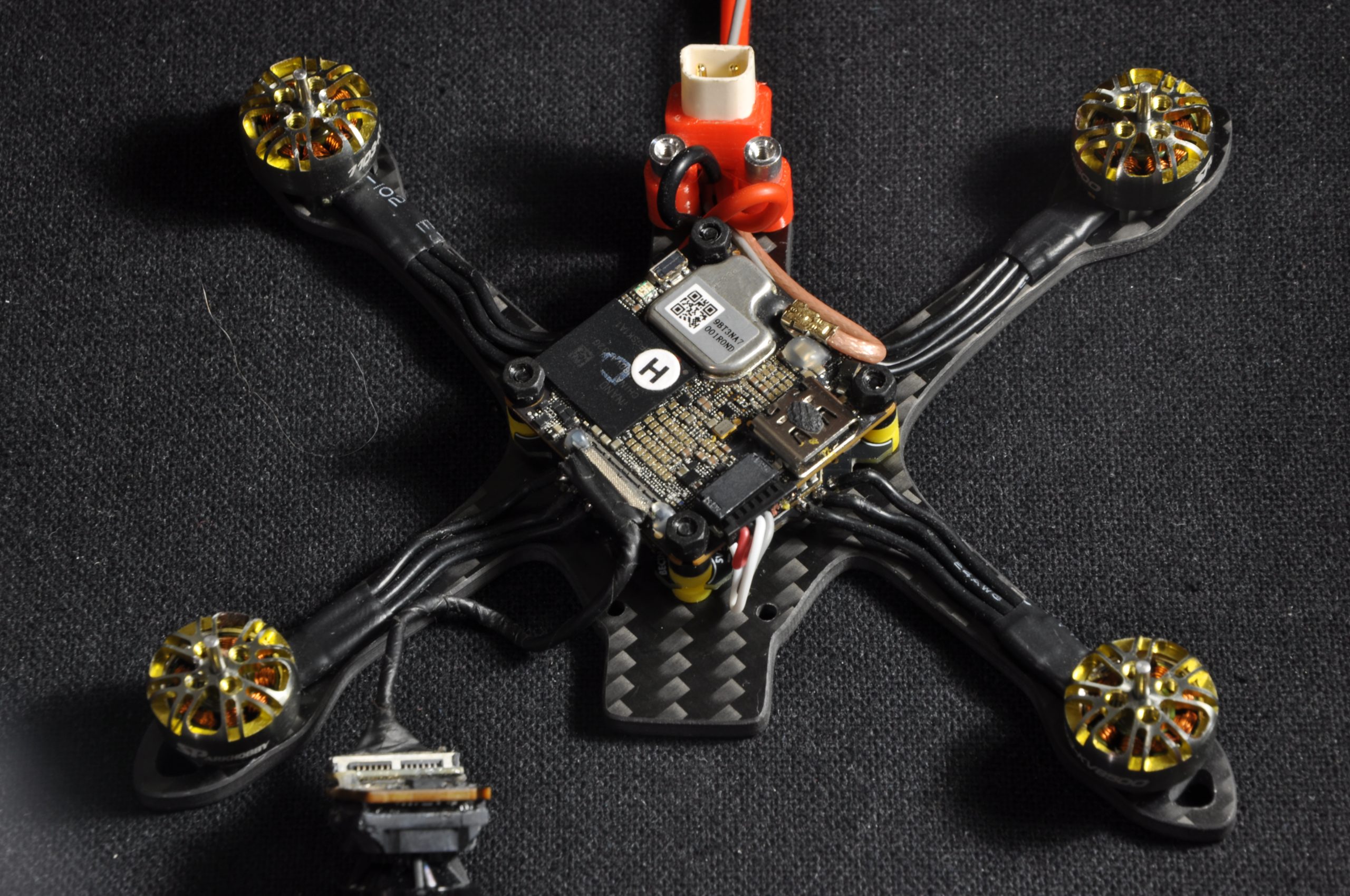
Step 4: Installation of the DJI O4
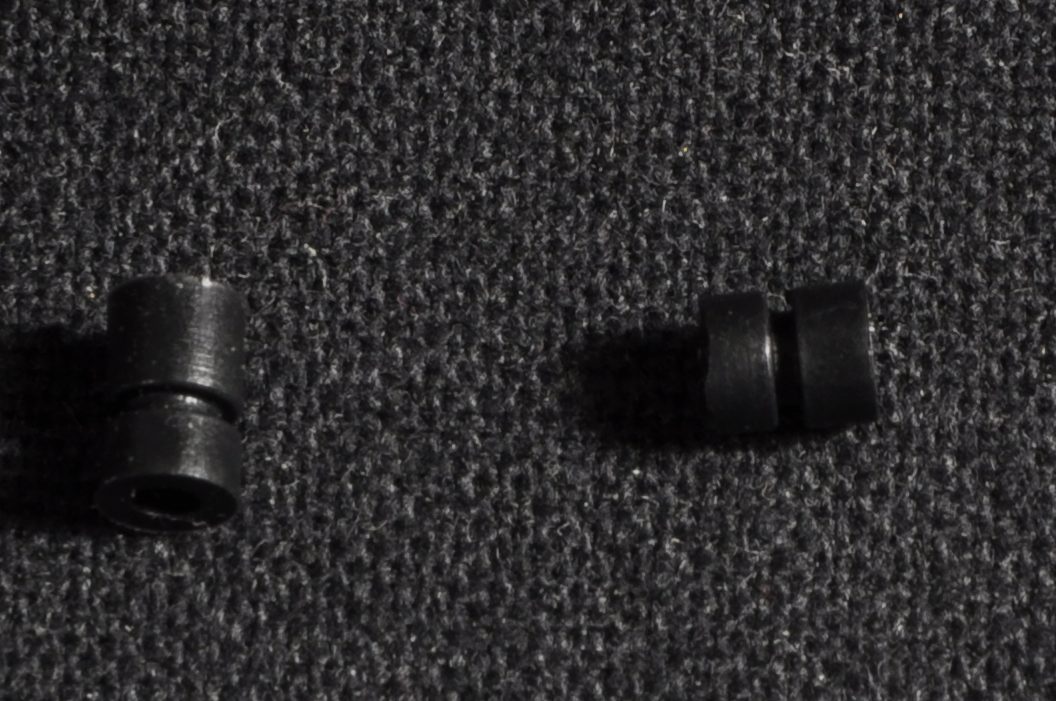
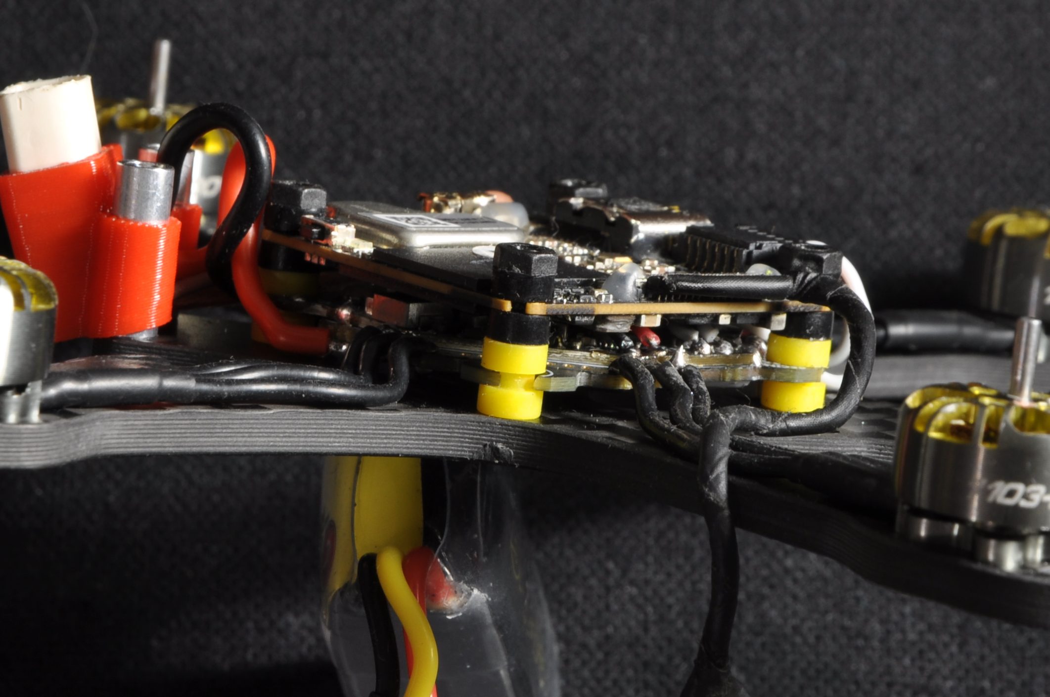
Before installing the VTX, slightly shorten its rubber dampeners («gummies») by cutting them, so they fit correctly between the frame standoffs.
Place the DJI O4 on the stack. It is mandatory to route its power cable between its two printed circuit boards (PCBs). Verify that no components touch or rub against each other, then secure everything with four nylon nuts.
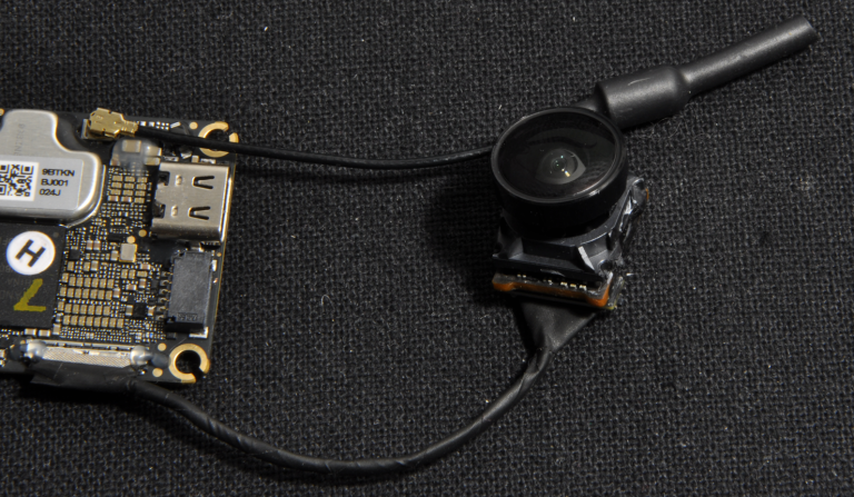
Step 5: Mounting the camera and 3D prints
Insert the camera into its TPU mount, then connect it to the VTX (always ensuring the cable passes under the O4).
Assembly tips:
- Press the aluminum standoffs into the TPU parts before screwing them onto the frame.
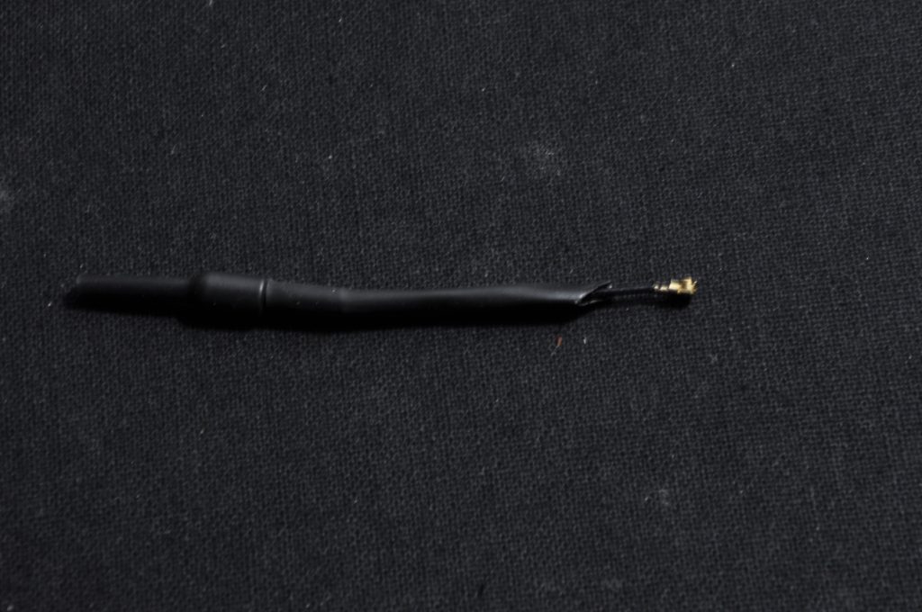
- To stiffen the VTX antenna, a piece of heat shrink tubing can be added. Cutting it at an angle will facilitate its insertion into the TPU (this step is unnecessary if the «backpack with integrated antenna» option was chosen).
- Screw in the 4 standoffs without applying excessive force, as aluminum remains a fragile material.
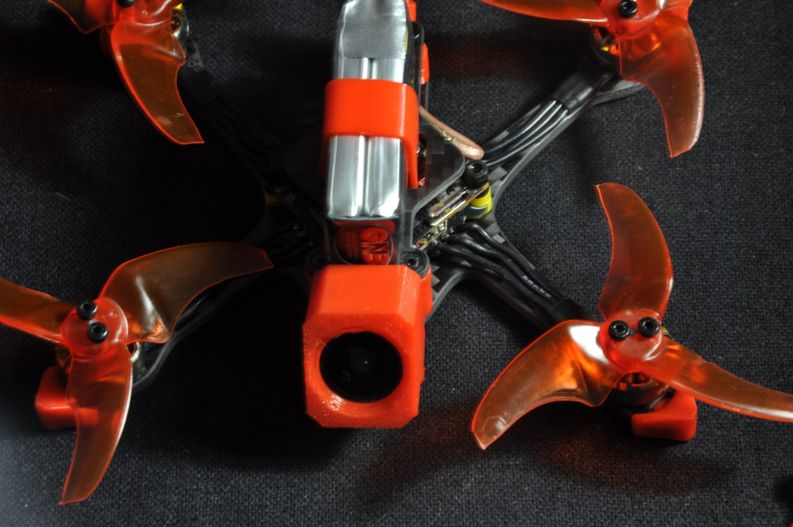
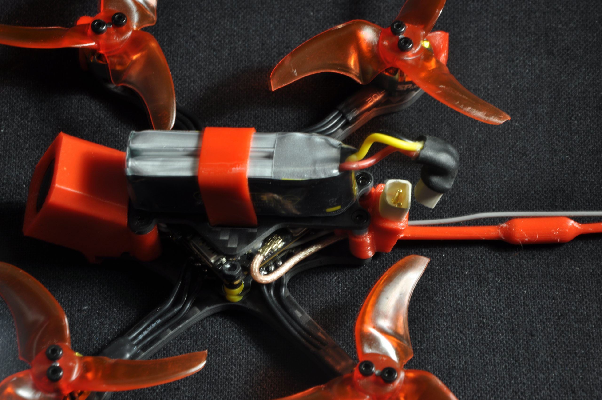
Step 6: Final assembly
Install the top plate and proceed with mounting the propellers.
ℹ️ Note: It is highly recommended to screw the propellers on. Although this adds a slight amount of weight, this method eliminates a large portion of in-flight vibrations.
Step 7: Betaflight & Bluejay Configuration
The hardware assembly is complete. It remains to configure the software part. Here is the procedure to follow:
- Update the firmware of the ESCs (Bluejay) and the flight controller (Betaflight).
- Bluejay settings: Increase the Maximum Startup Power (necessary because 8500kv motors on 2S draw a lot of current at startup) and set the PWM frequency to 24kHz to maximize torque.
- Verify the order and direction of rotation of the motors in Betaflight.
- Configure the UART corresponding to the DJI O4 as well as the OSD.
- Assign the radio controller switches (Arming, Turtle mode / Crashflip, etc.) in the «Modes» tab.
- Adjust the PIDs according to the desired flight behavior.
- Optimization: It is recommended to disable RC smoothing and enable Bidirectional DSHOT for better performance.